| Architectural Layout & Operational Design Strategy |
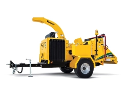
| The Vermeer BC1000E is a heavy-duty, stationary electric-powered drum-style brush chipper purposefully engineered for high-volume organic waste reduction, biomass processing, and biofuel production environments. Designed specifically as a zero-emission alternative to internal combustion machinery, this unit completely eliminates jobsite exhaust and fuel management issues while delivering substantially lower hourly operational costs than equivalent diesel or gasoline configurations. The structural backbone relies on a rugged fabricated steel Z-section chassis measuring 0.3" x 7" (.76 cm x 17.8 cm), equipped with three integrated hoist hook rings for secure crane rigging and stationary factory installation. Power delivery is split between two independent dust- and weather-proof Siemens electric motors housed within a heavy-duty, anti-vandal all-steel enclosure rated at IP55 protection. Processing performance is driven by a high-inertia 20-inch (50.8 cm) cutting drum paired with an extra-wide 12-inch by 17-inch infeed throat, reducing the overhead labor needed for structural material trimming. The material intake is continuously optimized by Vermeer's patented SmartFeed system, an automated load-sensing control loop that tracks motor amp draw to dynamically stop or reverse the 400 lb feed roller under heavy crushing resistance. Emergency compliance is integrated via a comprehensive three-tier system, including a adjustable-sensitivity lower mechanical stop bar, a multi-position top control rail, and dual-sided green hold-to-run safety restart switches. |
| General Dimensions, Weights & Structural Housing |
| Overall Length - Compact Profile (Infeed Table Raised) |
110.2 in (280 cm) |
| Overall Length - Operational Profile (Infeed Table Lowered) |
140 in (355.6 cm) |
| Overall Chassis Operational Width |
67 in (170.2 cm) |
| Overall Structural Machine Height |
98.4 in (250 cm) |
| Total Base Unit Operating Weight |
4409.2 lbs (2000 kg) |
| Chassis Main Frame Composition |
Fabricated structural Z-section plate measuring 0.3 in x 7 in (0.76 cm x 17.8 cm); includes 3 hoist rings |
| Infeed Table Sheet Steel Thickness |
0.2 in (0.5 cm) thick steel plate |
| Primary Drum Electric Drive Motor (Siemens Core Power) |
| Motor Manufacturer and Housing Style |
Siemens high-efficiency industrial motor; mounted inside a heavy-duty all-steel weather enclosure |
| Average Energy Consumption / Output Rating |
Draws approximately 45 kW per hour under normal duty cycles; gross output equivalent to 73.8 hp (55 kW) |
| Environmental Enclosure Protection Rating |
IP55 (dust-proof and completely sealed against multi-directional water spray and wood dust accumulation) |
| Electrical Specifications @ 50 Hz Operational Grid |
Input Voltage: 380V AC; Phase configuration: 3-Phase; Full Load Current: 103 Amps; Synchronous Speed: 1480 rpm |
| Electrical Specifications @ 60 Hz Operational Grid |
Input Voltage: 380V AC; Phase configuration: 3-Phase; Full Load Current: 103 Amps; Synchronous Speed: 1770 rpm |
| Secondary Infeed System Electric Motor (Hydraulic Pump Power) |
| Subsystem Application |
Electric driver dedicated to the high-torque active material feeding hydraulic pump |
| Gross Output Power Rating |
4 hp (3 kw) |
| Enclosure Rating and Phase |
IP55 structural sealing; 3-Phase array |
| Electrical Specifications @ 50 Hz Operational Grid |
Input Voltage Options: 380V AC or 415V AC; Full Load Current: 6.3 Amps; Synchronous Speed: 2860 rpm |
| Electrical Specifications @ 60 Hz Operational Grid |
Input Voltage: 380V AC; Full Load Current: 6.3 Amps; Synchronous Speed: 3460 rpm |
| Heavy-Duty Drum Cutting Mechanism Specifications |
| Maximum Log/Brush Processing Diameter Capacity |
12 in (30.5 cm) continuous logs; wide throat handles multi-branched logs easily |
| Cutting Drum Rotor Core Dimensions |
Diameter: 20 in (50.8 cm); operational width: 20 in (50.8 cm) |
| Drum Cylinder Wall Steel Thickness |
0.4 in (1 cm) plate steel |
| Operational Running Speed of Drum Rotor |
1997 rpm |
| Cutting Knife Geometry and Dimensions |
2 active knives; knife size metrics: 0.625 in x 4.5 in x 9 in (1.59 cm x 11.43 cm x 22.86 cm); thickness: 0.6 in (1.6 cm) |
| Knife Steel Material Matrix & Fasteners |
Premium heavy-impact A8 composition chipper tool steel; secured by 4 structural mounting bolts per knife |
| Knife Structural Configuration & Replacement |
Dual usable cutting edges per blade; equipped with an independent replaceable threaded knife mounting block |
| Discharge Air Impeller Paddles |
3 integrated discharge paddles utilizing a heavy-duty weld-on attachment method |
| Bedknife (Anvil) Geometrical Matrix |
Base dimensions: 3.5 in x 17.25 in (8.89 cm x 43.82 cm); structural thickness: 1 in (2.5 cm) |
| Bedknife Base Material & Wear Edges |
1018 composition carbon steel; features 4 usable cutting edges per block for maximum runtime rotation |
| Rotor Service Interlock Mechanism |
Heavy mechanical safety locking pin assembly supporting 2 distinct service pinning positions |
| Hydraulic Circuit & Proportional Intake Rollers (Feed System) |
| Active Proportional Intake Roller Design |
1 single heavy-duty horizontal upper feed roller; diameter: 20 in (51 cm); total deadweight: 400 lbs (181.4 kg) |
| Intake Roller Compression Downforce Load |
350 lbs (158.8 kg) downforce compression rating |
| Minimum Structural Clearance (Roller to Drum) |
1 in (2.5 cm) hard proximity stop point |
| Feed Roller Hydraulic Motor Specification |
1 White high-torque hydraulic motor; structural displacement rating: 28.3 |
| Linear Feeding Proportional Intake Speed |
105 ft/min (32 m/min) maximum high-speed intake velocity |
| Infeed Table & Safety Hopper Geometry |
Table Width: 52 in (132.1 cm); Table Length: 32 in (81.3 cm); Material Guide Board Height: 12 in (30.5 cm) |
| Infeed Throat Material Gate Dimension |
12 in x 17 in (30.5 cm x 43.2 cm) clear intake clearance matrix |
| Infeed Table Elevation Height Above Ground |
26 in (66 cm) low-profile ergonomics deck level |
| Infeed Hazard Safety Distance (Pinch Point) |
Distance from absolute outer table rim edge to the internal roller pinch centerline: 66.5 in (168.9 cm) |
| Hydraulic Loop Layout Configuration |
Open-center hydraulic flow path design |
| Main Pump Fluid Delivery Performance |
2.7 gpm (10.2 L/min) output flow rate at maximum operational RPM |
| System Maximum Working Relief Pressure |
2500.4 psi (172.4 bar) overpressure threshold setting |
| Fluid Tank Reservoir & Dual Filtration Arrays |
7 gal (26.5 L) tank capacity; 10-micron fluid filter inline on return loop paired with a 100-micron pump suction strainer |
| Directional Control & Cooling Profile |
Equipped with manual directional control valves; open loop runs without an integrated auxiliary oil cooler |
| Master Electrical Control Enclosure Hardware (Control Box) |
| Internal Low Voltage System Loop |
12V / 24V DC dual-voltage matching transformer logic |
| Control Box Physical Enclosure Dimensions |
Height: 49.2 in (125 cm); Width: 15.7 in (39.9 cm); Length: 33.8 in (85.9 cm) |
| Total Standalone Weight of Control Enclosure |
88 lbs (39.9 kg) |
| Telemetry Module Placement |
Rigidly mounted directly on the rear frame adjacent to the infeed table for immediate access during operation |
| Integrated Automated Safety Controls & Operator Protection Loop |
| SmartFeed Amp-Sensing Control System |
Patented digital load-sensing network: monitors the active current (Amps) of the main Siemens motor. Automatically halts or cycles the feed roller into reverse during crushing resistance peaks. |
| Bottom Feed Stop Bar (BFSB Subsystem) |
Standard 2 in (5.1 cm) diameter emergency stop bar constructed from high-tensile 11 GA sheet steel. Strategically positioned for knee/leg trip actuation by the operator. |
| BFSB Mechanical Actuation & Sensitivity Arrays |
Required Trip Pressure Force: 34 lbs (15.4 kg). Dual sensitivity selection settings: Normal Sensitivity mode operates at a 22-degree arc, Reduced Sensitivity mode at a 12-degree arc. |
| 4-Position Top Feed Control Bar |
Standard high-reach multi-mode control bar wrapping the hopper top frame. Manual selector detents: Emergency Stop (E-stop), Forward, Stop, Reverse. Requires 34 lbs (15.4 kg) of activation force. |
| Circuit Reset Safety Activation Method |
Dual green hold-to-run override buttons located on both sides of the infeed table housing; requires manual engagement to clear active trips and reset forward roller feed. |


 RU
RU


 Брошюра