| Architectural Design & Operational Processing Strategy |
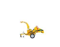
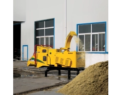
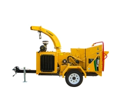
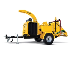
| The Vermeer BC2100XL is a flagship, high-capacity, heavy-duty mobile drum-style brush chipper engineered for large-scale land clearing, commercial forestry, and high-volume whole-tree processing of materials up to 21 inches (53.3 cm) in diameter. Constructed for extreme industrial workloads, the heavy chassis frame is fabricated from structural steel C-channels measuring 2.5 x 8.75 inches (6.4 x 22.2 cm), combined with a high-strength towing tongue (2.5 x 4.5 x 0.38 inches) and a robust pintle ring coupling. Ground logistics are managed via a heavy-duty Rogers Willex tandem load-sharing leaf-spring suspension system rated at a massive 17,636 lbs (8,000 kg), which distributes machine weight evenly to decrease ground pressure in soft jobsite conditions and ensures premium towing stability. Power is supplied by a 6-cylinder Cummins QSB 6.7L Tier 3 turbocharged diesel engine generating 275 hp and 730 ft-lb of torque. The powertrain employs a simplified Clutchless PTO direct-drive belt design with an automated belt tensioner, completely eliminating mechanical over-center clutches and reducing long-term maintenance costs. The processing intake features the largest-in-class infeed table (72-inch width) integrated with a Dual-Horizontal Offset feed roller configuration where the lower roller is nested 10.75 inches (27.3 cm) forward toward the table edge, enabling the rollers to aggressively grab whole trees with a theoretical combined pulling force of 10,000 lbs (4,536.9 kg). Materials are securely gripped by triangular surface nubbins and end-face sprocket-style gear teeth rings that act as anti-wrapping vine rippers. Crucial production efficiency is enhanced by the patented SmartCrush hydraulic system, which applies automatic high-force downward pressure (up to 3,500 lbs) via hydraulic cylinders once the upper roller remains raised for over 4 seconds, and the automated SmartFeed load-sensing management loop which moves jammed material back and forth. The rear chassis is anchored during operation by dual hydraulic outriggers, and secondary rigging operations are handled by a 4,000 lb hydraulically pivoting winch boom. |
| General Dimensions, Weights & Structural Trailer Framework |
| Overall Length - Transport Configuration (Feed Table Up, Tongue In) |
235 in (596.9 cm) |
| Overall Length - Operational Configuration (Table Down, Tongue Extended) |
259 in (657.9 cm) |
| Overall Chassis Operational Width |
95.8 in (243.2 cm) |
| Overall Structural Machine Height (To Top of Discharge Chute) |
116.5 in (295.9 cm) |
| Total Base Unit Weight - 275 hp Engine Option (Excluding Auxiliary Winch) |
16800 lbs (7620.4 kg) |
| Static Vertical Hitch Load Capacity (Tongue Weight) |
2410 lbs (1093.2 kg) — requires heavy commercial towing vehicle |
| Chassis Main Longitudinal Frame Structure |
2.5 in x 8.75 in (6.4 cm x 22.2 cm) structural steel C-channel profile |
| Towing Tongue Dimensions and Extension Profile |
2.5 in x 4.5 in x 0.38 in (6.4 cm x 11.4 cm x 1 cm); fixed non-extending layout for AUS markets |
| Hitch Coupler Interface and Storage Components |
3 in (7.6 cm) heavy-duty pintle ring hitch coupler; lockable steel toolbox integrated into the chassis |
| Axle Suspension Subtype Layout & Manufacturer |
Tandem load-sharing independent leaf-spring suspension axle assembly; manufactured by Rogers Willex |
| Total Suspension Axis Rated Weight Capacity |
17636 lbs (8000 kg) |
| Wheel and Tire Specification Metrics |
Heavy commercial tires: 235/75R17.5 (Load Range J); steel rims: 17.5 in x 6.75 in (6-on-8.1 inch bolt circle) |
| Brake Type and Road Light Configuration |
Full commercial Air Brakes equipped with ABS; all-weather LED tail and marker lights mounted high for structural protection |
| Stabilization Subsystem |
Standard rear-mounted dual hydraulic outriggers operated from the primary rear control station |
| Turbocharged Diesel Engine Infrastructure (Cummins QSB 6.7L) |
| Make, Model and Emission Compliance Matrix |
Cummins QSB 6.7L Turbo; EPA Tier 3 / EU Stage IIIA certified emissions |
| Cylinder Array and Combustion Profile |
6 cylinders; in-line configuration, high-pressure common rail, turbocharged and charge-air cooled |
| Maximum Gross Output Power |
275 hp (205.1 kw) @ 2200 RPM (215 hp and 250 hp configurations available) |
| Maximum Peak Engine Torque Output |
730 ft-lb (989.8 Nm) |
| Fuel Reservoir Capacity and Fuel Type |
65 gal (246.1 L) total tank volume; engineered for low-sulfur or ultra-low-sulfur diesel fuel |
| Maximum Full-Load Fuel Consumption Rate |
15.6 gph (59.1 lph) at 100% continuous output load |
| Air Intake Filtration Subsystem |
2-stage heavy-duty dry-element Fleetguard OptiAir 1300 series filtration core |
| Lubrication Parameters and Volumetric Oil Capacity |
API CH-4/SJ service classification; spin-on oil filter; engine oil capacity with filter: 16 qt (15.1 L) |
| Cooling System Infrastructure and Alternator |
Liquid-cooled radiator circuit; coolant capacity: 7.3 gal (27.6 L); 95 amp Delco-Remy charging alternator |
| Cooling Fan Configuration Matrix |
26 in (66 cm) high-velocity suction fan pulled toward a radiator screen with 5/64" holes to ease daily cleanout debris management |
| Engine Operational Limits and Noise Threshold |
Maximum continuous operating incline angle: 30 degrees; operational acoustic signature: 86 dB(A) |
| Mechanical Powertrain & Shaft Bearing Components |
| Power Take-Off (PTO) Configuration |
Clutchless PTO direct-drive layout; completely eliminates high-maintenance mechanical over-center clutches |
| Drivetrain Engagement Interface |
Automated heavy mechanical belt tensioner idler assembly acting on 5V wedge-profile high-torque drive belts |
| Main Cuttershaft Supporting Bearings |
2 Linkbelt self-aligning spherical roller bearing assemblies; shaft bore diameter: 2.4 in (6.2 cm) |
| Bearing Mechanical Structural Load Capacities |
Dynamic Load Rating: 31400 lbs (14242.8 kg); Static Load Rating: 53500 lbs (24267.2 kg) |
| Heavy-Duty Drum Cutting Mechanism Specifications |
| Maximum Log/Brush Processing Diameter Capacity |
21 in (53.3 cm) maximum capacity thickness |
| Cutting Drum Cylinder Rotor Dimensions |
Rotor core diameter: 36 in (91.4 cm); operational width profile: 28 in (71.1 cm) |
| Drum Cylinder Wall Structural Steel Thickness |
0.5 in (1.3 cm) thick plate steel |
| Operational Running Speed of Drum Rotor |
1084 rpm |
| Total Cutting Drum Weight (With Shaft Assembly) |
1500 lbs (680.4 kg) — provides high kinetic cutting inertia |
| Cutting Knife Array Quantity and Thickness |
4 active cutting knives; structural blade thickness: 0.6 in (1.6 cm) |
| Knife Geometrical Size & Composition Matrix |
5 in x 14 in (12.7 cm x 35.6 cm); premium heavy-impact A8 composition chipper tool steel |
| Knife Structural Fastening and Usable Lifespan |
Secured by 6 high-tensile bolts per knife; 2 indexable usable cutting edges; replaceable threaded structural knife block |
| Discharge Air Impeller Paddles and Volumetric Output |
4 integrated heavy-duty kinetic paddles utilizing a structural weld-on attachment method; airflow output: 3600 cfm |
| Bedknife (Anvil) Structural Dimension Metrics |
Base dimensions: 3 in x 27.5 in (7.6 cm x 69.9 cm); features 4 indexable usable wear edges |
| Rotor Maintenance Interlock |
Heavy mechanical safety lock pin supporting 4 independent service pinning positions for blade replacement |
| Hydraulic Proportional Material Feed System |
| Proportional Material Intake Layout Configuration |
Dual-horizontal offset feed rollers; lower intake feed roller is nested 10.75 in (27.3 cm) forward toward the table edge |
| Combined Theoretical Feeding Pulling Force |
10,000 lbs (4536.9 kg) of high-torque pulling force to swallow full logs and bushy structures |
| Upper Intake Feed Roller Specifications |
Diameter: 19 in (48.3 cm); width: 40 in (101.6 cm); roller weight: 972 lbs (440.9 kg); 8 rows of aggressive gripping teeth |
| Lower Intake Feed Roller Specifications |
Diameter: 11 in (27.9 cm); width: 40 in (101.6 cm); 12 rows of teeth; equipped with 2 cleanout tracking knives |
| Feed Roller Hydraulic Motor Subsystems |
2 independent high-torque proportional Eaton hydraulic motors; structural displacement rating: 4.9 CID |
| Mechanical Compression Force & Proximity Limits |
Hydraulic cylinder downforce applying up to 3500 lbs (1587.6 kg) of base clamping load; 10 in (25.4 cm) mechanical proximity safety stop limit |
| Intake Surface Gripping Engineering |
Triangular shaped surface nubbins spaced 4.5" (11.4 cm) apart on the upper roller and 3" (7.6 cm) apart on the lower roller; sprocket gear teeth side rings act as vine rippers |
| Linear Material Feeding Intake Speed |
100 ft/min (30.5 m/min) |
| Infeed Table Deck Geometry and Sheet Profiling |
Table Width: 72 in (182.9 cm) — largest in class; Table Length: 60.5 in (153.7 cm); deck sheet thickness: 0.4 in (1 cm) |
| Infeed Throat Capacity & Entry Geometry |
Throat intake opening gate dimensions: 40 in x 24 in (102 cm x 61 cm); structural curtain entry height: 38.5 in (97.8 cm) |
| Infeed Deck Elevation Height and Hazard Distance |
Elevation above ground level: 30.8 in (78.2 cm); safety distance from absolute outer table rim edge to internal roller pinch centerline: 60.5 in (153.7 cm) |
| Hydraulic Architecture and Pump Performance |
Open-center hydraulic path; pump flow rating at max engine RPM: 13 gpm (49.2 L/min); equipped with dedicated heavy-duty Oil Cooler |
| System Pressure Ratings and Core Filtration |
24 gal (90.9 L) tank capacity; system relief valve threshold: 2750 psi (189.6 bar); auto-reverse loop pressure ceiling: 2550 psi (175.8 bar) |
| Hydraulic Fluid Care and Filtration Arrays |
10-micron fluid filter inline on return loop; 100-mesh pump suction strainer; Vermeer Hy-Power 68 oil |
| Discharge Shroud System (Chute Structure) |
| Discharge Point Target Elevation Height |
116 in (294.6 cm) standard height; adjustable height discharge chute assembly available as a factory option |
| Structural Steel Chute Sheet Thickness Metrics |
Bottom structural plate: 0.1 in (0.3 cm); top dome plate: 0.2 in (0.5 cm); side walls: 0.1 in (0.3 cm); deflector flap: 0.1 in (0.2 cm) |
| Chute Rotation Array and Control Drive |
270 degrees total horizontal sweeping rotation operated via full hydraulic motor drive |
| Chute Clog Mitigation Management |
Equipped with a mechanical hinged lower door (Chip Chute Cleanout Door) for rapid debris cleanout access |
| Optional Fully Hydraulic Winch Package Specifications (Auxiliary Rigging) |
| Winch Boom Assembly and Rope Parameters |
Heavy welded plate structural steel boom with integrated hydraulic lift cylinders; 9/16 in (1.4 cm) double-braided DYNEEMA core rope (150 ft / 45.7 m length) |
| Kinetic Drag and Speed Performance Metrics |
Maximum line pull force capacity: 4000 lbs (1814.4 kg); winch drum input speed: 51 rpm; hydraulic relief valve ceiling: 1900 psi (131 bar) |
| Operator Control Modes & Swivel Alignment |
Hydraulic controls for rope feed (In/Out) and boom position (Up/Down); winch line guide tip roller features 360-degree free swiveling loop; Vermeer standard chain choker |
| Electrical Control Enclosures, Telemetry & Operator Safety Protection Loop |
| SmartFeed Automated System Monitoring Logic |
Patented digital load-sensing network: monitors engine RPM and automatically stops or reverses intake rollers under high log resistance. Automatically senses intake jams and shifts material back and forth to clear blocks without operator intervention. Includes 3 droop settings. |
| SmartCrush Intelligent Clamping Logic |
Automated hydraulic downforce assistant: once the upper roller scales over thick branches for more than 4 seconds, the circuit automatically activates high downward hydraulic pressure to crush forked or branchy limbs. Down-pressure automatically ceases once the roller descends within 1.5 in (3.8 cm) of the table bed. |
| Master Vehicle Controller & Gauge Telemetry Panel |
Vermeer C148 master electronic control unit; integrated analog/digital panel tracking engine speed (tachometer), operational hour meter, trip meter, coolant temperature, engine oil pressure, battery voltage, active ECU fault codes, and dedicated engine warning/shutdown light blocks. |
| Radio Remote Control System Capabilities (Optional) |
Wireless handheld transmitter mirrors controls for: engine speed throttling, hydraulic discharge chute rotation, feed roller directions (Forward, Stop, Reverse), SmartCrush down-pressure selection levels, SmartFeed droop parameters, and wireless emergency engine stop. |
| Critical Preventative Machine Safety Shutdowns |
Automated safety cutoffs instantly stall the engine during high coolant temperature, high intake manifold temperature, or low engine oil pressure states |
| Mechanical Hazard Entry Safeguards |
Standard 2 in (5.1 cm) diameter emergency bottom feed stop bar (BFSB) fabricated from 11 GA steel with dual side green hold-to-run reset loops. Dual side-mounted manual feed control bars (Side Feed Control Bar) positioned for immediate reach to manual stall or override roller flow directions. |
| Chassis System Voltage and Battery Array |
12-volt primary DC network loop powered by 2 independent Group 31 starter batteries rated at 950 Cold Cranking Amps (CCA) each |
| Factory Optional Packaging Available |
| Custom fleet industrial paint finishes, Adjustable height discharge chute extensions, Full wireless radio remote control arrays, Rear-mounted hydraulic stabilizing outriggers, Extended Vermeer Protection (EVP) commercial warranty packages, and factory planned preventative maintenance service contracts. |


 RU
RU