| Architectural Engineering & Core Performance Mechanics |
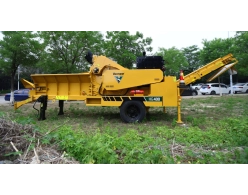
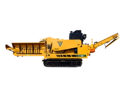
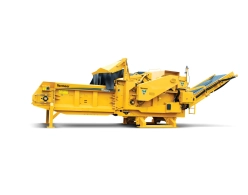
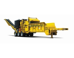
| The Vermeer HG4000 is a heavy-duty, high-capacity towable horizontal grinder engineered for high-volume organic waste processing, land clearing, and wood-biomass recycling operations. Built upon a rigid monocoque unit-body frame with a heavy fabricated tongue, the machine offers maximum structural durability during intense milling applications. To comply with varying transport regulations and fleet preferences, the HG4000 is offered in two main chassis configurations: a 3-axle Pintle hitch trailer (featuring a centralized axle configuration to decrease tongue load) and a 2-axle 5th Wheel semi-trailer setup. Both configurations are equipped standard with an Electronic Braking System (EBS), European-compliant underrun protection structures, and a multi-voltage 12-24V LED trailer lighting system. The machine is powered by a 6-cylinder Caterpillar C13B turbocharged industrial diesel engine delivering 536 hp (399.7 kW) and an exceptional peak torque rating of 1807 ft-lb (2450 Nm) while meeting Tier 4 Final / Stage V emissions rules. Power transfer to the milling chamber is governed by a hydraulic-operated twin-disc dry clutch assembly activated via a simple electronic push-button interface. The critical thermodynamic cooling package is handled by a Flexxaire variable-pitch axial cooling fan with automatic hydraulic reversing functionality to purge airborne wood dust from the radiator, supplemented by an independent variable-speed electric fan for the Charge Air Cooler (CAC). The material infeed setup features a massive 15 ft (4.6 m) long open table with a 3.5 cu m capacity, using integrated flared side walls and bolt-on corner flares to facilitate uniform loading of tangled brush and logs. The conveyor floor utilizes a welded steel slat chain with a dome-top cleat design that narrows the gap before the anvil to enhance end-product sizing consistency and eliminate material propping. An innovative structural overlap between the infeed floor and the single-piece discharge belt ensures that fine spillage under the anvil is caught and immediately deposited back onto the discharge conveyor for maximum jobsite cleanliness. Material intake is driven by a 2700 lb (1224.7 kg) upper feed roller with a 28-inch (71.1 cm) diameter, driven by a fixed-displacement hydraulic motor paired with an aggressive 34.2:1 planetary reduction gear. The roller features 10 serrated steel bars and an adjustable hydraulic downforce system equipped with an on-demand "Crush Boost" function via the remote control, which momentarily spikes the downward force to crack and process large structural logs. The machine features a highly adaptable modular millbox that allows operators to interchange between two distinct rotor types: a 5370 lb (2435.8 kg) Series III Duplex Drum featuring 9 independent reversible hammers and 18 indexable wide cutter tips driven at 1113 RPM (generating a tip velocity of 9615 ft/min), or a 4707 lb (2135.1 kg) specialized Chipper Drum spinning at 842 RPM with 12 fully adjustable knives made from premium A8 mod steel to produce micro-chips from 0.125 in to 1 in. Sizing calibration is handled by a heavy dual-screen setup constructed of 0.75-inch (1.9 cm) thick abrasion-resistant steel providing a combined screening area of 3131 sq in (20200 sq cm). The reversible screens are housed under a top-hinged millbox lid that opens independently of the feed roller assembly, granting ground-level access for swift maintenance and tool changes. Product discharge is handled via an extra-wide 48-inch (121.9 cm) single-piece continuous conveyor belt that eliminates internal belly-to-loadout transfer chokepoints, operating at a linear speed of 625 ft/min to lift finished mulch or chips to an impressive 14 ft (4.3 m) discharge height for direct loading into standard semi-trailers. All system operations are controlled via a sealed membrane CAN bus keypad on the unit body or a long-range wireless LCD radio remote control capable of multi-channel frequency tuning up to a 300 ft (91.4 m) operating perimeter. |
| General Weight Parameters, Structural Footprint & Axle Loads |
| Maximum Transport Length (Pintle Hitch Modification) |
37 ft (11.3 m) |
| Maximum Transport Length (5th Wheel Modification) |
32 ft (9.8 m) |
| Maximum Operational Setup Length (Conveyor Extended) |
52 ft (15.8 m) |
| Maximum Transport Width |
8.2 ft (2.5 m) |
| Maximum Transport Height |
13 ft (4.0 m) |
| Maximum Total Gross Weight (Pintle Configuration) |
55155 lbs (25017.9 kg) |
| Maximum Total Gross Weight (5th Wheel Configuration) |
52910 lbs (23999.6 kg) |
| Maximum Vertical Tongue Weight Load (Pintle Hitch) |
2200 lbs (997.9 kg) |
| Maximum Vertical Tongue Weight Load (5th Wheel Kingpin) |
15432 lbs (6999.8 kg) |
| Maximum Combined Axle Group Load Capacity (Pintle Configuration) |
52910 lbs (23999.6 kg) |
| Maximum Combined Axle Group Load Capacity (5th Wheel Configuration) |
37478 lbs (16999.7 kg) |
| Chassis Ground Clearance Profile (Option One) |
17 in (43.2 cm) |
| Acoustic Signature Rating (Sound Power) |
112.3 dB |
| Engine Powertrain & Thermodynamic Subsystem Specifications (CAT C13B) |
| Engine Manufacturer, Model and Mechanical Layout |
Caterpillar C13B (Inline 6-cylinder turbocharged industrial diesel engine) |
| Emission Certification Regulatory Rating |
Tier 4 Final / Stage V Compliant (EU Road & Off-Road certified) |
| Maximum Gross Engine Power Output |
536 hp (399.7 kW) |
| Maximum Peak Engine Torque Output |
1807 ft-lb (2450.0 Nm) |
| Fuel Tank Volumetric Capacity |
200 gal (757.1 L) |
| Fuel Type Specification |
Ultra-low sulfur diesel (ULSD) |
| Diesel Exhaust Fluid (DEF) AdBlue Tank Capacity |
17.3 gal (65.5 L) |
| Maximum Fuel Consumption Rate at Peak Load |
27.2 gph (103.0 L/h) |
| Recommended Oil Specification and Viscosity Grade |
API CJ-4 (or higher classification), viscosity rating SAE 15W-40 |
| Total Engine Oil Volume Including Filters |
9 gal (34.1 L) |
| Air & Oil Filtration Component Specifications |
Dry-type air cleaner with primary and secondary elements and built-in restriction indicator; full-flow, spin-on oil filter canister |
| Cooling Medium and Total Subsystem Fluid Capacity |
Liquid cooled; nitrite-free, pre-diluted 50/50 glycol mix antifreeze; 10.5 gal (39.7 L) engine + radiator volume |
| Maximum Air-to-Boil Ambient Threshold Temperature |
128°F (53°C) |
| Charging Alternator Specifications |
24 V DC system voltage; 250 Amp high-output rating |
| Primary Engine Radiator Cooling Fan Subsystem |
Flexxaire variable-pitch axial fan assembly featuring automated hydraulic blade-reversal purge cycles |
| Charge Air Cooler (CAC) Intercooler Fan Subsystem |
Electric-driven fan unit featuring automated variable-speed regulation |
| Main Power Take-Off (PTO) Clutch Assembly Type |
Hydraulic-operated twin-disc dry clutch; activated via electronic push-button cockpit interface |
| Auxiliary Drive Belt System Configuration |
Heavy-duty V-belt layout |
| Standard Infeed Processing Table & Feedcrush System Mechanics |
| Infeed Table Hopper Processing Dimensions |
Table Width: 60 in (152.4 cm); Hopper Bed Depth: 20 in (50.8 cm); Table Bed Length (Option One): 15 ft (4.6 m) |
| Total Infeed Table Hopper Volumetric Capacity |
4.6 cu yd (3.5 cu m) |
| Material Feed Loading Height (Table Top to Ground Line) |
7.6 ft (2.3 m) |
| Hopper Flare Structural Construction |
Integrated rigid steel frame wall with bolt-on corner expansion flares |
| Infeed Conveyor Bed Design and Material Composition |
Welded steel slat chain layout featuring dome-top profile cleats; dragging deck constructed of welded structural steel plate |
| Conveyor Roller Profiles and Core Drive Mechanism |
Drive roller: Welded steel assembly; front tension idler roller: Self-cleaning spiral auger design; driven by a high-torque fixed-displacement hydraulic motor |
| Infeed Throat Processing Gateway Dimensions |
42 in (106.7 cm) opening height x 60 in (152.4 cm) opening width |
| Upper Compression Feed Roller Geometry Dimensions |
Working roller width: 56 in (142.2 cm); external outer tooth path diameter: 28 in (71.1 cm) |
| Upper Feed Roller Structural Component Weights |
Total combined roller weight including heavy pivoting tracking arm: 2700 lbs (1224.7 kg) |
| Feed Roller Material and Gripping Interface Design |
Fabricated from heavy-walled steel; fitted with 10 longitudinal steel bars with a sharp serrated bar design |
| Feed Roller Drive Motor & Reduction Transmission |
Fixed-displacement hydraulic motor mated to a planetary reduction drive; gear ratio rating: 34.2:1 |
| Compression Pressure Control & Crush Boost System |
Hydraulic downforce pressure is fully adjustable; remote-controlled "Crush Boost" function momentarily commands peak hydraulic downforce to fracture rigid intake logs |
| Intake Safety Deflectors & Blast Curtains |
Standard heavy-duty Thrown Object Deflector guard; variable position adjustment shield; flexible containment curtain manufactured from thick rubber |
| Milling Rotor Variant Option 1 — Series III Duplex Drum Assembly |
| Milling Chamber Entry Portal Area (Millbox Opening) |
60 in (152.4 cm) width x 31 in (78.7 cm) clearance height |
| Total Weight and Physical Sizing of Duplex Rotor |
Total drum weight: 5370 lbs (2435.8 kg); core drum wrapper diameter: 22.5 in (57.2 cm); outer knife-tip rotation diameter: 31.3 in (79.5 cm); total cutting path width: 60.9 in (154.7 cm) |
| Drum Structural Outer Skin Shell Thickness |
1.5 in (3.8 cm) solid plate steel wrapper for high inertia retention |
| Rotor Rotational Speed & Cutter Velocity Metrics |
Operational drum speed under full load: 1113 RPM; linear cutting tip velocity (Tip speed): 9615 ft/min (2930.7 m/min) |
| Main Rotor Shaft Supporting Bearing Assembly |
Double-row spherical roller bearing configuration; inner race bore diameter: 4.3 in (10.9 cm); dynamic structural load capacity: 136000 lbs (61688.6 kg) |
| Cutting Layout Matrix and Pin Sizing Data |
Features 9 independent processing hammers; 18 indexable cutter tips; standard profile shape: Premium wide; central hammer retention pin sizing: 2 in (5.0 cm) diameter x 75.3 in (191.0 cm) length |
| Internal Debris Clearance and Purging Fan Layout |
Four-blade spiral fan scavenging assembly |
| Milling Rotor Variant Option 2 — Industrial Chipper Drum Assembly |
| Total Weight and Physical Sizing of Chipper Rotor |
Total drum weight: 4707 lbs (2135.1 kg); core drum wrapper diameter: 27.3 in (69.3 cm); total cutting path width: 60 in (152.4 cm) |
| Drum Structural Outer Skin Shell Thickness (Chipper) |
1.3 in (3.3 cm) solid plate steel wrapper |
| Chip Sizing and Processing Cut Depth Adjustability |
Fully adjustable depth of cut range: from 0.125 in (0.31 cm) up to 1 in (2.5 cm) |
| Chipper Knife Matrix Sizing and Pockets |
Total knives installed: 12 units; 12 structural receiving pockets; knife thickness rating: 0.625 in (1.6 cm); total indexable usable cutting edges per knife: 1; fixed via 2 structural grade bolts per knife |
| Knife Metallurgy and Structural Security Features |
Manufactured from high-wear premium A8 modified chipper steel tool alloy; drum features integrated Replaceable Threaded Knife Blocks |
| Chipper Rotational Speed & Cutter Velocity Metrics |
Operational drum speed under load: 842 RPM; linear knife tip speed when calibrated for a 1-inch uniform wood chip: 7274 ft/min (2217.1 m/min) |
| Shaft Geometry and Chipper Bearing Infrastructure |
Double-row spherical roller bearing assembly with a 4.3 in (10.9 cm) inner race bore and a dynamic load rating of 136000 lbs (61688.6 kg); central shaft core diameter: 5 in (12.7 cm); shaft attachment type: Keyless bushing assembly |
| Material Sizing Screens & Millbox Chamber Liners |
| Screen Structural Configuration, Thickness and Metallurgy |
Dual-screen system loop; screens manufactured from high-grade abrasion-resistant steel plate; plate thickness rating: 0.75 in (1.9 cm); total assembly weight varies by mesh selection |
| Combined Screen Surface Processing Area |
Total cumulative screen area surrounding the lower drum arc: 3131 sq in (20200.0 sq cm); total screens: 2 units; single-sided (1) indexable processing profile (reversible and interchangeable layout) |
| Chamber Hood Upper Shield Liner (Millbox Lid Liner) |
Replaceable abrasion-resistant steel plate liner; structural dimensions: 62 in (157.4 cm) width x 21.5 in (54.6 cm) height x 16 in (40.6 cm) internal curvature radius |
| Anvil Assembly Design, Sizing and Wear Face System |
Box beam-style anvil design featuring adjustable and bolt-on replaceable wear surfaces; structural dimensions: 6.1 in (15.6 cm) height x 73.5 in (186.7 cm) length x 13.6 in (34.5 cm) width |
| Finished Product Discharge System — Single-Belt Design |
| Discharge Conveyor Overall Physical Geometry |
Total continuous structural length (single-piece belly to loadout design): 20 ft (6.1 m); conveyor belt width: 48 in (121.9 cm) |
| Conveyor Belt Layering, Strength and Cleat Profile |
Heavy-duty 3-ply rubber belt fabric construction; structural strength class rating: 330# tensile index; surface profile: V-cleat pattern to prevent material fallback |
| Belt Splice Hardware and Underside Support Layout |
Heavy-duty R2 stainless steel cable mechanical belt splice lock; total lower return rollers: 3 units |
| Conveyor Roller Sizing Profiles & Bearing Flanges |
Tension idler roller outer diameter: 12 in (30.5 cm); idler shaft supporting bearings: 1-15/16 inch size fitted in an industrial 4-bolt flange housing; standard head drive roller diameter: 12.8 in (32.5 cm) |
| Conveyor Drive Transmission & Magnetic Separation |
Driven by a fixed-displacement hydraulic motor; linear belt velocity speed: 625 ft/min (190.5 m/min); optional magnetic head drive pulley (metal extraction) diameter: 12.8 in (32.5 cm) |
| Conveyor Discharge Drop Point Elevation (Load Height) |
14 ft (4.3 m) high vertical drop path; optimized for uniform filling of high-sided open semi-trailers |
| Hydraulic Circuit Infrastructure — Implement & Conveyor Loops |
| Main System Fluid Reservoir Volume & Oil Sizing |
Total tank capacity: 7.7 gal (29.1 L); recommended fluid medium: Vermeer Hypower 68 hydraulic oil; filtration method: Dual return filters in return block; 1 core hydraulic oil cooler radiator |
| Implement Controls Valve Bank & Loop Logic |
Equipped with two Danfoss PVG-32 proportional control valve blocks; circuit configuration: Open-loop, pressure and flow compensated layout |
| Implement Main Hydraulic Pump Profile Specs |
Variable-displacement axial piston pump assembly; volumetric flow rate at max engine RPM: 25.3 gpm (96.5 L/min); system safety circuit relief pressure setting: 3000 psi (206.8 bar) |
| Discharge Conveyor Dedicated Hydraulic Sub-Loop |
Circuit configuration: Independent Open-loop layout; pump type: Fixed-displacement gear pump assembly |
| Conveyor Fluid Flow, Relief Threshold & Motor Class |
Conveyor pump flow rate at max engine RPM: 16.3 gpm (61.7 L/min); conveyor sub-circuit relief pressure setting: 2900 psi (200.0 bar); conveyor motor series designation: TH |
| Power Take-Off Clutch Actuation Fluid Circuit |
Autonomous hydraulically-activated variable pitch system architecture |
| Electrical Distribution, Telemetry Dashboards & Remotes |
| System Operating Voltage & Battery Bank Output |
24 Volt DC core network voltage; powered by 2 heavy-duty 8D-MHD batteries delivering 1400 Cold Cranking Amps (CCA) each; circuit safety: Fused protection throughout |
| On-Frame Stationary Operator Control Interface |
Integrated all-weather station housing an LCD digital telemetry screen tracking engine data, machine vitals, and diagnostic Operational Faults; physical dials/gauges are omitted; user switches are sealed membrane CAN bus keypads |
| Wireless Radio Frequency Remote Control Subsystem |
Handheld wireless industrial radio transmitter featuring an integrated LCD telemetry screen displaying engine diagnostics, machine status, and fault logs; controls configured via a sealed membrane keypad; maximum wireless operating perimeter range: 300 ft (91.4 m); powered by 6 AA standard batteries; supports multi-channel tuning up to 50 individual radio channels |
| Trailer Running Gear, Axle Assembly & Chassis Options |
| Chassis Structural Frame & Fender Construction |
Chassis frame built as a rigid unibody unit body construction; heavy fabricated steel tongue extension; fenders made from formed plate steel, bolt-fastened and individually replaceable |
| Hitch Interface Mechanical Layout Selections |
4 unique factory variants: 5th wheel kingpin hitch, 5th wheel kingpin hitch with hydraulic creep drive (site maneuverability system), Pintle hook ring hitch, or Pintle hook ring hitch with hydraulic creep drive |
| Trailer Axle Group, Suspension Type & Manufacture |
Suspension type: Multi-leaf heavy duty mechanical Spring suspension; axle group manufacturer: Hutchens Industrial, Inc.; rated structural capacity per single axle: 22400 lbs (10160.5 kg) |
| Chassis Axle Array Count by Towing Selection |
Semi-trailer 5th wheel layout version: Dual (2) axles; drawbar Pintle hitch trailer version: Triple (3) axles with a centralized grouping |
| Wheel Rims and Tire Sizing Profile |
Heavy-duty tire specification: 385/65R22.5 high-load flotation highway tires; wheel hub rims: Lightweight, high-strength forged Aluminum |
| Auxiliary On-Board Maintenance Air Compressor Subsystem |
| Compressor Block Brand and Engine Specifications |
Compressor pump head brand: Mi-T-M; powered via a dedicated independent 9 hp (6.7 kW) Honda single-cylinder gasoline utility engine |
| Pneumatic Output Volume & Pressure Index |
Maximum working pressure ceiling: 125 psi (8.6 bar); maximum volumetric air flow rate: 17.2 cfm (0.5 cmm) |
| Pneumatic Air Accumulator Tank Fluid Volumetric Capacity |
Storage receiver capacity on 5th wheel semi-trailer frames: 21 gal (79.5 L); storage receiver capacity on Pintle hitch trailer frames: 31.7 gal (120.0 L) |


 RU
RU